"Operation MOONBOUNCE"
1959-1964
After the launch of Sputnik 3, May 15, 1958, the satellite tracking was no longer a
novelty as the rest of the world and our government had come up to speed.
The next two years were taken up with extra interest in Science Fairs, and more "special projects"
for the community. Ham radio training and the studying to get FCC Commercial licenses continued as well.
The club was given the surplus Link trainer which they restored, and that led to aircraft training
under a new program headed up by Brother Paul Koller. Mike Stimac immediately started working with
Paul, and the rest of the radio gang got involved.
Bob Leskovec, completing his year as president of the club was hired to work at
Lost Nation Airport in Avionics in the Spring of 1959 while others in the group
like Mike Cegelski, and Dave Mazi, were learning
navigation and maintenance and how to actually fly airplanes!
Every year from the beginning of the club in 1951 there was always a new group being
mentored through the process by the older students, and the ongoing process of everyone
building radio transmitters, getting receivers, and putting up antennas to get their home
stations on the air. Then there was the friendly competition of amassing radio contacts
with far off places, and exchanging and collecting of colorful “QSL” verification cards.
It goes without saying that these highly-motivated students were equally concerned with
keeping up their studies and getting good grades, because they were already thinking like
adults about long-term goals that included college or military aspirations.
-- So much to do, and so little time, and everyone had to keep moving on.
When the SJHRC became the first civilian satellite tracking station in October of 1957,
the club hardly realized all the implications of the feat. One of these implications
was destined to later turn into one of the largest and most unique research projects
ever to pass through the high school. This project consisted of successfully reflecting a
radio signal off of the moon and hearing the return signal here on earth.
The operation was soon appropriately titled “Project Moonbounce”.
Commercial and military research endeavors in this regard already established that the signal
path losses to the moon and back were barely surmountable with the best equipment at their
disposal. They could build huge antenna arrays, and use very high powers to see if they
could establish a transmission path to relay communications from one end of the earth to
the other by bouncing the signals off some reflector in outer space. Of course the most
obvious one was the moon, while NASA, (which was created by President Eisenhower in July
of 1958 in response to the wake-up call of Sputnik), started plans to launch the “ECHO”
high-altitude balloons. At that time the only “long-distance” telephone connection to
Europe was still the trans-Atlantic undersea cable!
Hams were more limited in the power they could use, so the problem was even more challenging.
It was known that weak CW and radio teletype (RTTY) signals had the best chance of being retrieved
from the noise, and these hams did not need to relay voice, just a signal stream that would
confirm that they were successful. A low-noise amplifier and a high-power transmitter would
be required, as well as a large antenna array that could be remotely aimed to track the moon,
and a control system to keep those antennas aimed, and automate the sending and receiving
process.
This was clearly a project that would require the concentrated work of many participants,
and if it were to be done in any reasonable time frame, there would be no time to build
everything from scratch.
So as the plan started to evolve, there were many aspects, none necessarily more important
that another, and effort went in whatever direction seemed to produce results at any given
time. A control system was being conceived to handle such functions as switching between
transmit and receive, pulsing the coded signal, logging the operation, and performing other
odd jobs. Of course there were no computers or anything past mechanical calculators at the
time. The only obvious electro-mechanical “state-of-the art” machine for this task was a
“teletype” machine, and specifically one with a paper tape puncher and reader. The punched
paper tape was the “memory” that could hold the “programming”.
Many letters were written and companies contacted, and finally in late May of 1959 came
some good news. The Teletype Corporation in Chicago, who had heard of the club’s Sputnik
tracking work, backed this as a “college research project” and donated two brand new Model
28 machines, valued at 7,000 dollars. Now the students had to come up to speed on
something they had only been reading about.
The “goals” in those days (not unlike today) were to be able to get to try all the latest
gadgets, but unlike today, it was not as easy as buying a cellphone with more “features”
and just pushing buttons!
One actually had to put some effort into hooking things up and making them work.
So in ham radio, one path was to get equipment and figure out how to operate as many
“modes” as possible, like AM and FM, and Single Sideband, and then do it that on higher
and higher frequencies, where there were formidable challenges in building the transmitters and
receiving converters.
So it was a “given” that first thing to do with these teletype machines was to hook
them up so they “talked” to each other. Next, an adapter was designed and built so
that a teletype (TTY) could be hooked up to transmit and receive signals over the ham radio
and communicate with other hams using a mode called (RTTY), short for “radio-teletype”.
These things alone were not simple and learning to make all this work by building and debugging
the interface circuits was most exciting and satisfying, and highly educational.
During the summer of 1959 many of the students were away, but others, headed up by Bob Kozar,
started to formulate a plan. A frequency of 145.2 MHz was chosen after careful consideration.
Kozar and Stimac worked up a chart to determine the signal losses over the EME path, calculating
the coefficient of reflection as the signal impinged on, and the echo dispersed from, the moon’s surface.
Hams at the time were limited to a transmitter input power of 1,000 watts. After contacting
several of the obvious sources for such a transmitter, someone directed Mike Stimac to the Bird
Electronics Corporation, who agreed to let the club have an old commercial FM transmitter which
was not being used. (Bird Electronics was already a world-famous company that made RF wattmeters
and "dummy loads" for the industry, and used many and various types of high-power transmitters to
develop and test their products.)
Within a few days, the transmitter was converted to the desired frequency and running a full 1000
watts input, and around 500 watts output as indicated on a Bird Model 43 Wattmeter connected to
a dummy load --both items also kindly donated by the company.
Similarly the group started sketching out the first antenna system and the large metal base of
metal work that would need to be constructed to distribute the weight on the roof of the building.
Mike Stimac again tapped his “resources” and the rest of the summer was spent collecting donations
of structural metal and hauling the welder to the roof and starting to build the base, and beginning
structure. Of course, there were always other duties and assignments that the brother had to perform,
and called people away, so the work was not continuous.
The newly elected club officers for the 1959-60 class-year were Ed Miller as president, Joe Marsey
as vice-president, John Kuzmic, VP in charge of meetings, and Bob Kozar Treasurer.
The officers conducted a weekly meeting consisting of electronic demonstrations and practice together
with some radio theory. Through this extensive study the club planned to attain its 100th licensed
member since the founding of the club in 1951. To date, there were 84 licensed members and the
expectation for a 100th licensee seemed not far off.
But with the fall semester of 1959 the flying program was really “taking off”, and with so many
of the students pulled over to take advantage of that, there was not much time and interest in
pushing the moonbounce work. As usual in Cleveland, winters kill any much chance of doing
outside work, so the spring semester was not conducive to getting much done on the antennas either.
It was soon April of 1960, and the last of the main group who had participated in Sputnik, including
Bob Leskovec were busy with completing things for their graduation in May. --but not without Bob
donating the first two, 10-element, 2 meter (150 MHz) antennas, which that job at Lost Nation Airport
allowed him to buy. That contribution to the project helped keep others interested and it was quickly
determined that at least two more of these antennas would be needed.
But for the others, school was not out until June, and when Bob Kozar headed up a successful
presentation to the Student Council, many people outside the radio club began to appreciate this
was a “school” project that should be funded. Hence they got the money to acquire the latest
“high tech” Tapetone 2-meter converter with a 417A low noise front-end amplifier. The latter
was a special tube developed by Western Electric for their cross-country microwave telephone relay stations.
The converter mainly fed into their prized National Radio HRO-60 receiver that had been used for Sputnik.
Other gear was similarly acquired, such as more antennas and the special low-loss
antenna-connecting wire called “silver-plated ladder line,” along with a military
surplus RTTY converter, and a signal generator.
That summer, Bob Kozar, who had no car, would regularly find a way to get to the school,
keeping the guys inspired and working, as Mike Stimac was called
away a lot. But together, they erected the first antenna base, mast, and array of 4, 10-element
2 meter band antennas, and connected it all using the low loss “ladder line”.
The control system came together was well. For one of the methods, they did not use RTTY two-tone, or frequency-shift
keying FSK modulation. They used simple CW, just turning the transmitter on and off, and
listening in between. The punch tape was fed through the teletype machine and instructed the
system automatically to “key” the rig, sending out the letter M several times, and switching
the system so it would listen in between. It would take roughly 2-1/2 seconds for an echo to
be heard from the moon. The punched tape would also automatically send the call letters and
then start the process all over again. Instead of a long reel of tape, the sequence was worked
out in a section which was then cut and spliced to form a repeating loop!
So by the end of the summer of 1960, they had a working system and spent many hours trying to
hear the echo from the moon, but with no results.
NASA launched "Echo" --the high-altitude balloon Mylar-skin reflector satellite on May 13, 1960.
The mission failed. Then on August 12, 1960 they managed to get up the replacement Echo-1A
which was thereafter commonly referred to as Echo-1. The guys had some success! –and got
echoes back from that 100-foot diameter target, but still nothing back from the moon.
Not allowed by the FCC to increase power, they needed a larger antenna and a more-sensitive,
lower-noise receiver. For the latter, the only solution was to go to the ultimate technology of
the day, just being developed, a “parametric amplifier, with little chance of getting their hands
on one.
Again, the science fairs, and aircraft program needed attention as well as mentoring the next
bunch to get their licenses. During the cold winter months, a new antenna was designed. It’s
structure was found to be so large that they would need a strong 55-foot vertical tower to
support a 50-foot long horizontal tower acting as a rigid boom, which in-turn supported four,
20-foot masts holding an 10-element beam antenna at each end, for a total of eight.
It was time for another “seek and you shall find” mission to obtain equipment. The day saver
this time turned out to be the Village Cab Company, who donated an old radio tower that had
fallen down and was a bit twisted and bent. After a few trips with a pickup truck to move
it in sections, and a lot of bending, bracing, and welding, they had the 55-foot tower to use for the vertical
support. The Euclid Fish Company donated the 50-foot tower. These were businesses in the
neighborhood who had sons and brothers that went to St Joe’s, and knew about the
accomplishments of the radio club.
It was early 1961 when they began fabricating a 45-foot square base system to distribute the
weight on the roof. This was made out of structural steel which was welded to construct a base form
capable of supporting the massive structure. First,
every length had to be cut and prepared and gotten up to the roof, as well as the heavy welder.
Needless to say, a several students also learned how to weld. The structure was doubly large
because it was necessary to have a way to pivot and lower the main tower so that the entire top
structure could be attached and then have the tower pivot back up to the vertical position.
It also needed to have provisions to rotate the main boom horizontally and vertically so that
the antennas could be aimed at the moon. It was estimated the entire assembly came to about 4 tons!
The description may be hard to picture, but fortunately some photos were taken and found in the
archives. While the design itself proved adequate from a support standpoint, what was overlooked
was a factor called “wind resistance”.
By June, it was ready to go up, and that process alone took a couple weeks and the help of several
devoted individuals, including newer students and guys from the group that had been working on this
project for some time: Bob Kozar, Bob Tombascio, John Kuzmic, Jeff Jaquays, Ted Alexander,
Joe Kostansek, Terry Sejnowski, Dan and Dennis Sweeney, Paul Kadis, and Tom Satyshur.
Along the way, incidentally, that 100th license was indeed granted, with the honor going to Dan Sweeney!
During a late summer storm, the antenna suffered wind damage, and that took over a month to repair,
so it was not until November that they were able to get it back up. But in Cleveland the “gales of
November” are notorious, and soon it was again damaged. Then, in the process of trying to lower
the unit for repairs, when horrendous strain is put on the cabling system, a turnbuckle broke, and
disaster struck! In an instant the whole thing lay in a shambles on the roof, soon documented with
before-and-after-pictures in the Cleveland Press. To make things worse, Mike Stimac who was now was a
fully-license pilot with passenger rating as a result of the flying program, was being re-assigned
to start a badly-needed flying mission in Africa! Medicine and doctors needed to be transported
in the bush, and more pilots needed to be trained.
But with Mike gone, the troops stayed motivated and went back to the drawing board, studying more
about antennas, and learning there was a way increase the antenna gain but not increase the structure
any further. That consisted of cross-polarizing the antennas and feeding the vertically polarized
elements 90 degrees outof phase with the horizontal elements. That would have the same effective
gain for the reflection but be only half the physical size.
Interviewed in 2007, Bob Kozar gave this summary:
“We rebuilt the tower assembly after the crash. It was a thing of beauty. The vertical tower came
from the Village Cab Company. The horizontal tower came from Euclid Fish Co. The transmitter came
from Bird Electronics (the people that make the classic Bird 43 Thruline Wattmeters). The transmitter ran 500 watts
CW output. I think the beams were eight 21-element Hy-Gain Yagis that we modified with added
vertical elements to get cross-polarization. I remember that we calculated 21dB total gain from
the array, which is huge by any standard. We fed the array with silver-plated ladder line to
minimize the loss. We engineered the matching transformers between beams and between the feedline.
It actually worked. We had a 1.15:1 SWR on dry days, a little higher when it rained.”
"We swept the antenna horizontally and vertically, but we never had any evidence of reflected signal.
Nonetheless, knowing what I now know about the real world of project engineering, that was really quite a feat.”
One only needs to look at the pictures!
The Moonbounce Gang: (Help us complete this list!)
Bob Kozar
John Kuzmic
Dan Sweeney
Ted Alexander
Dennis Sweeney
Paul Kadis
Tom Satyshur
Jeff Jaquays
Joe Kostansek
Terry Sejnowski
Bob Tombascio
--and Mike Stimac
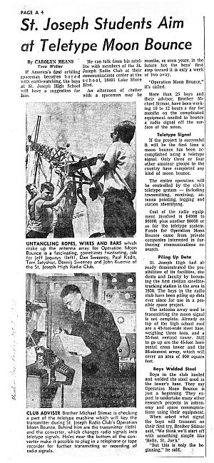
The above article appeared in the Cleveland Press,
Oct 2, 1961, using photos supplied by Mike Stimac.
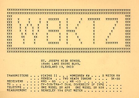
This equipment list was designed and printed on the Teletype!
|
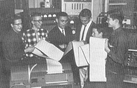
Mike Stimac and the guys examine output from the Teletype machines,
in this picture from the Norseman Dec 20, 1960
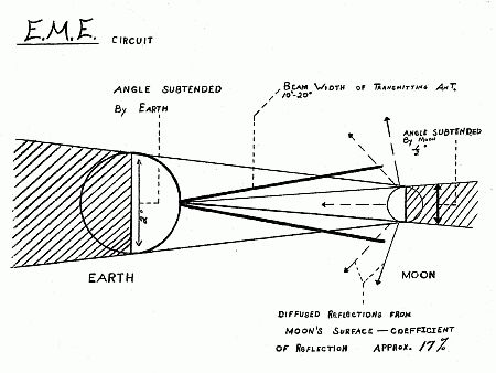
This diagram illustrates the EME path losses.
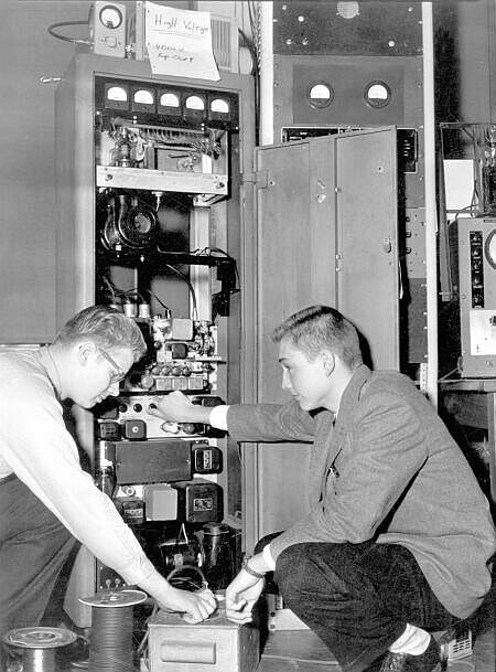
Bob Tombascio and Bob Kozar check out the 1kW, 2m
transmitter
connected to the Bird Model 43 Thruline
Wattmeter and Dummy Load atop the cabinet,
all donated by Bird Electronics Corp.
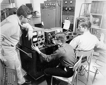
Using the military surplus gear, the
guys check out the system. The 1kW rig
is in the far back, center, and the Tapetone
converter
with low-noise 417A is in front
of John Kuzmic (right), connected
to the HRO-60 that Kuzmic is tuning. The Teletype is seen
at the lower left of the photo.
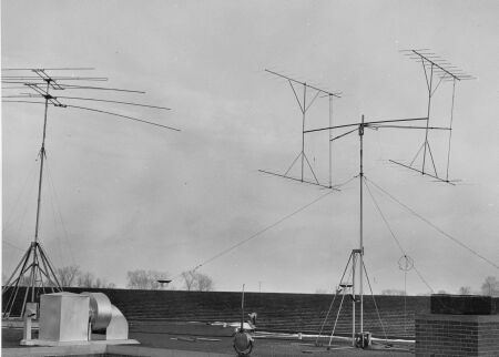
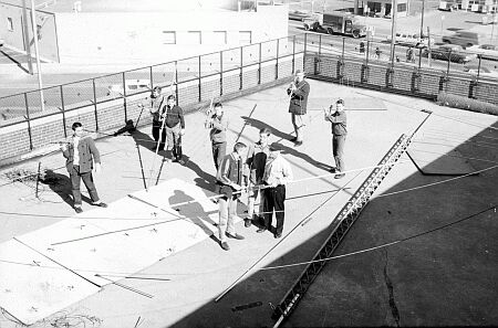
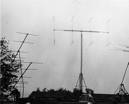
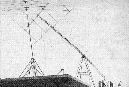
Left is the 20m and 15m homebrew beam antenna system
used to track Sputnik in 1957, and right, the first moon
bounce array, comprising four, 10-element Yagis,
which was not adequate for the job.
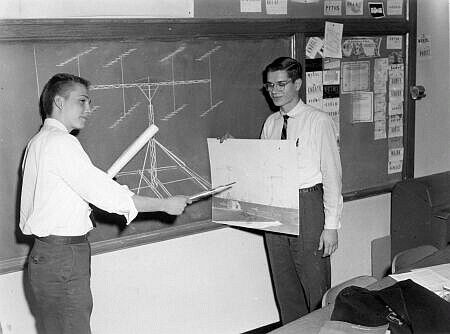
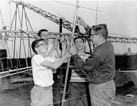
On the board, is the drawing of the proposed next antenna, as John Kuzmic,
(right) holds a picture of the present system, and Bob Kozar makes a presentation
to guests, including the student council, asking for funding and equipment donations.
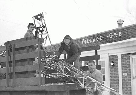
The guys pick up the first tower parts donated by Village Cab.
This was transformed into the 55-foot vertical section.
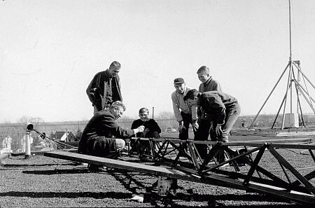
A few months later, they have the boom prepared, made out of
a second tower donated by Euclid Fish
and start to ready the
8, Modified 21-element Yagi's.
Here, the have hauled the items to the upper roof.
Part of the 55-foot tower is mounted to the pivot point on the base
support system, and tilted down as they complete adding
the rest of the sections. Another picture in this series was
published in
a Cleveland Press story on October 2, 1961.
(L-R) are Jeff Jaquays (up in back),
Dan Sweeney, Paul Kadis,
Tom Satyshur, Dennis Sweeney, John Kuzmic.
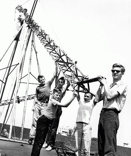
The 50-foot boom has been added to the top of the tower, and now
they are starting to mount the individual beam antennas.
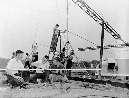
Here they continue attaching the modified 21-element Yagis.
Here it is! --A thing of beauty!
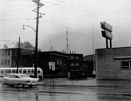
Long view with the guys on the deck and two on the tower.

The Cleveland Press printed these photos.
They were lowering the tower for repairs
and disaster struck!
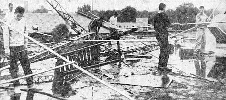
Amid the shambles, they pick up the pieces.
They will rebuild!
|